Interfaces
For both the DVL-A50 and the DVL-A125.
LED Signals
-
No green light: Power is off.
-
Fixed green light: The DVL is powering on. Depending on configuration it can take ~30-60 seconds to power on.
-
Flashing green light, mostly off (slow, every few seconds): DVL looking for bottom lock.
-
Flashing green light, mostly on (slow, every few seconds): DVL has bottom lock.
-
Flashing green light (fast, many times a second): DVL is in thermal shutdown.
Wiring interface
The tables below shows the pinning of the DVL interface.
| Interface | Color |
|---|---|
| Negative/Ground | Black |
| Positive (10-30V) | Red |
| ETH RX+ | Green/White |
| ETH RX- | Green |
| ETH TX- | Orange |
| ETH TX+ | Orange/White |
| UART TX | Brown/White |
| UART RX | Brown |
| Shielded wire | Naked (silver) |
Seacon MCOM8M Connector (DVL A50 only)
The table below shows the specific pinout for the Seacon MCOM8M connector.
| Interface | Pin |
|---|---|
| Negative/Ground | 1 |
| Positive (10-30V) | 2 |
| ETH RX+ | 3 |
| ETH RX- | 4 |
| ETH TX- | 5 |
| ETH TX+ | 6 |
| UART TX | 7 |
| UART RX | 8 |
Note
Power must be applied to the power terminals before applying voltage to UART pins
Shielded Cable Information
The DVL is equipped with a shielded cable that helps protect the communication and power lines from external electromagnetic interference (EMI) and radio frequency interference (RFI). Please note that the DVL electronics themselves are not internally connected to the shield; it is up to the user to decide whether and how to connect the shield.
Connecting the Shield
For optimal performance, especially when mounted on an ROV (Remotely Operated Vehicle) or AUV (Autonomous Underwater Vehicle), it is recommended to connect the shield to reduce the impact of interference on the communication and power signals. The most common connection methods are:
-
Chassis Ground:
Connecting the shield to the chassis of the ROV/AUV is the most typical practice. This method allows the shield to provide a path to ground for any noise or interference, helping to improve signal integrity. The ROV or AUV chassis often acts as a common reference point for grounding, which makes this a natural choice. -
Common Ground:
Alternatively, you can connect the shield to the common electrical ground of the ROV/AUV. This method may be used when the electrical and signal systems are designed to share a common ground. It helps ensure that interference is grounded without creating ground loops.
Recommendation
We recommend connecting the shield to the chassis ground of the ROV or AUV (if possible). This approach generally provides the best noise suppression by using the vehicle’s structure as a solid grounding point. However, if your system design prefers the use of a common electrical ground, that option can also be considered. Always ensure that the shield is grounded at one end only to avoid ground loops, unless your system design calls for grounding at both ends for specific applications.
Terminal Interface
The DVL-A50 has a 3.3 volt UART interface (5V tolerant).
| Settings | Value |
|---|---|
| Baud rate | 115200 |
| Data parity stop | 8N1 |
| Flow control | None |
Warning
There can be a momentary (<10 us) power spike (~5 V) on the UART lines when power is applied to the DVL, which may damage equipment which is not 5V tolerant.
See the DVL's serial protocol.
Ethernet Interface
See networking and the DVL's TCP protocol.
Code examples
Code for parsing of the data outputted by the DVL over TCP.
I/O interface
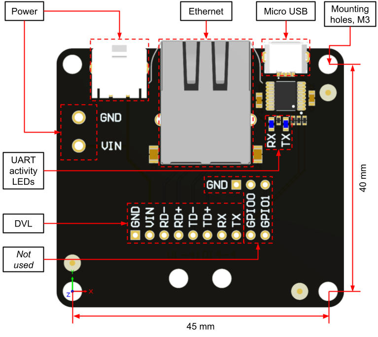
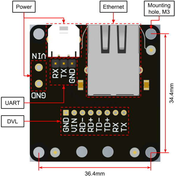
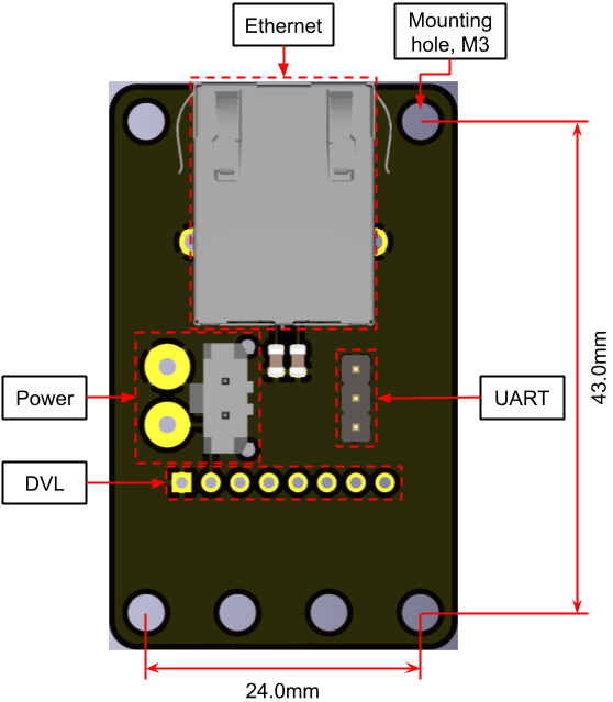
The I/O Interface provides a simple means of connection to the Water Linked DVLs. It provides magnetics for the ethernet connection and utilizes the Molex Micro-Fit 3.0 power connector (Part number: 436500204) which is standard for Water Linked products. Female connectors is listed under Mates with Part(s)
There currently exists three revisions of the I/O Interface. Revision 2 and 3 are electrically identical. Revision 4 has an integrated USB-to-UART interface and a micro USB port.
Revision 4

Dimensions: 50.6 x 47 x 18.6 mm (Width x Height x Thickness)
| Connector | Function | Comment |
|---|---|---|
| RJ45 (8P8C) | Ethernet | 10/100 BASE-T |
| Micro USB | Serial | FTDI based |
| Molex Micro-Fit 3.0 | Power | 10 - 30 VDC |
| 2x Ø1.5mm pads | Alt. power | Fits Würth 691137710002 |
Revision 3

Dimensions: 40 x 42 x 18.6 mm (Width x Height x Thickness)
| Connector | Function | Comment |
|---|---|---|
| RJ45 (8P8C) | Ethernet | 10/100 BASE-T |
| 3x1 header | Serial | TX, RX, GND |
| Molex Micro-Fit 3.0 | Power | 10 - 30 VDC |
| 2x Ø1.5mm pads | Alt. power | Fits Würth 691137710002 |
Revision 2

Dimensions: 30.6 mm x 50 x 18.6 mm (Width x Height x Thickness)
| Connector | Function | Comment |
|---|---|---|
| RJ45 (8P8C) | Ethernet | 10/100 BASE-T |
| 3x1 header | Serial | TX, RX, GND |
| Molex Micro-Fit 3.0 | Power | 10 - 30 VDC |
| 2x Ø1.5mm pads | Alt. power |
Note
The Molex Micro-Fit 3.0 on revision 2 is prone to damage by excessive sideways force. Take care not the yank the power cable when connected.